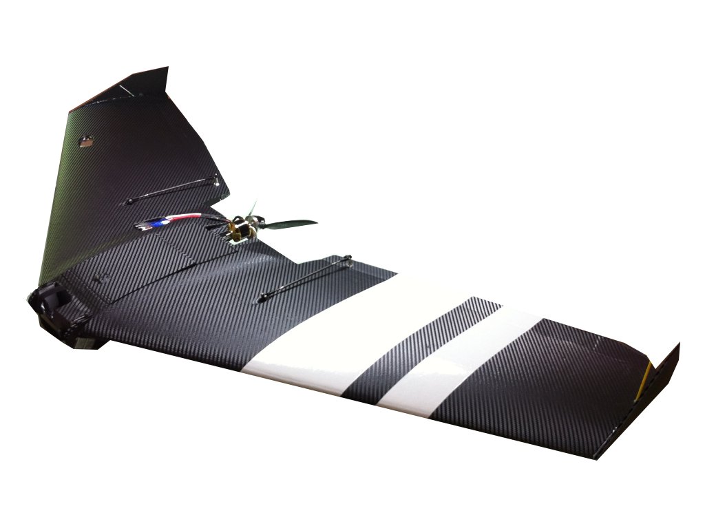
Installing Ruby in a Ritewing Zephyr II
|
Overview
Here are instructions, including videos and high definition closeup pictures, for installing Ruby in the Ritewing Zephyr II.
For installation in other aircraft, refer to Supported Aircraft or to General Installation Instructions.
|
| |
Mounting
Mounting the Ruby controller - most ideal
The most ideal location for the Ruby controller is alongside the batteries. The mass of the batteries minimizes vibration from the motor.
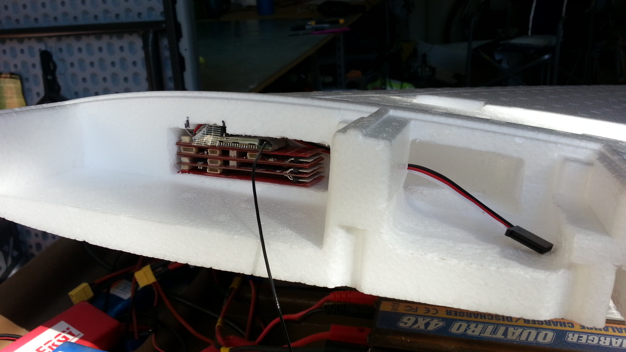
If your batteries occupy the entire compartment or you'd just like Ruby and its wiring tucked out of the way when you change batteries, you can cut a pocket as pictured here.
It can be difficult to cut out a nice pocket like this if you've already assembled the halves of your Zephyr, however. You might need to dig a pocket from the top or bottom of the wing.
A hot wire loop is the most ideal tool to creat pockets, but you can also just use knife and needle-nosed pliers to dig out the foam.
If you can't make the compartment snug enough to hold Ruby securely, our preferred method of mounting Ruby in a compartment is to wedge or hot-glue a block of EPP foam into that compartment so that it holds Ruby snugly in place. EPP foam is recommended because it is springy and reslilient. Some EPP blocks were shipped with your Ruby package.
Be sure that the Ruby controller is oriented parallel / orthogonal to the plane's flying axes. |
|
Mounting the Ruby controller - alternate locations
Don't mount in the aft compartment:
Ruby controller fits nicely in the Zephyr's aft compartment as shown [here], but we've found that this can be an undesirable location.
Vibration at that location tends to be much greater than elsewhere on the Zephyr because it is just inches away from the motor and the structural foam is relatively thin there. Ruby is pretty tolerant of vibration, but depending on how well your motor is balanced and the rotation speed of your motor, vibration in that aft compartment can become extreme to the point of reducing Ruby performance, or even disorienting the IMU. It may behave OK at first, but vibration may increase with wear and tear on prop, motor and fatigue of the foam.
You're free to locate the Ruby controller just about anywhere else on the Zephyr. You can put it in the fore or aft compartment, in a carved out pocket, or perhaps in an external "pod" attached to your Zephyr. Just be sure that:
- it is oriented parallel / "square" in one way or another to all plane axes
- there's no buffeting air pressure that might affect the barometric altimeter.
- it's within about 50 cm of the centerline
|
|
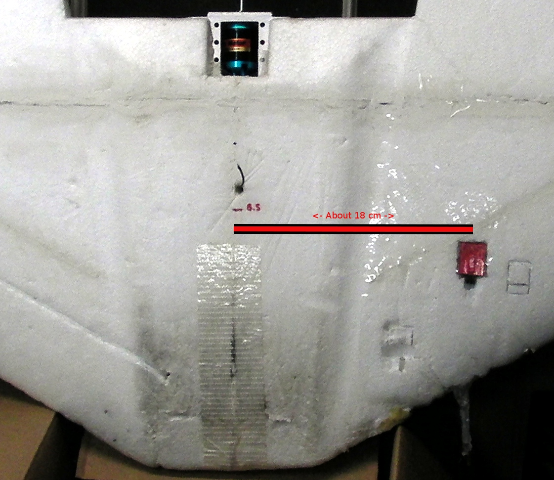
Mounting the airspeed / magnetometer
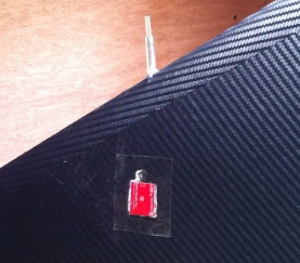
For best aesthetics and strength, install the airspeed / magnetometer sensor before covering if possible. If you've already covered your plane, you can simply cut a flap or hole in the covering.
The best place for the airspeed/magnetometer is on the bottom of the wing about 40 cm from the centerline, with the rear end of the board as far as possible from the leading edge, close to the spar. This is because it needs to be away from things such as high power lines or steel hardware that will tend to distort magnetic field. It also needs to be at least few inches away from the leading edge for better sampling of static air pressure.
Use a dremel router or loop of hot wire to dig out a pocket for the airspeed / magnetometer sensor just deep enough for the bottom of the sensor board to be flush with the bottom of the wing.
We provide 1/4 inch and 1/8 inch diameter tubing to create a pitot tube. The tubing is semi-flexible to minimize damage from impacts or snags that would occur with rigid tubing.
The thicker tubing provides stiffness at the base of the tube to ensure that it doesn't bend in the airflow at high speeds. It extends about 1 inch from the leading edge of the wing and about 1 inch into the wing. The thinner tubing is threaded through the thicker tubing (a little soapy water helps). It extends about 1/2 further from the end of the thicker tube and runs back to the airspeed / magnetometer sensor.
To accommodate this tubing, an 1/8 inch diameter hole or channel must be made through the foam from the leading edge of the wing into the chamber for airspeed sensor. The last 25mm of that hole or channel is widened to 1/4 inch in diameter to accommodate the 1/4 inch tubing.
For a clean hole, we use thin walled brass tube with sharpened edge attached to a hand drill or twisted by hand. A long drill bit will also work, however. You can also just dig out a channel in the wing for this tubing. The tube should project from the center / apex of the leading edge of the wing.
The pitot tubing slides onto to the port on the airspeed sensor that is furthest away from the sensor circuit board and cable connector. Note that one end of the supplied tubing is slightly flanged to allow it to slide over the nozzle.
The other port is left open to the ambient "static" pressure inside the chamber in the wing. Be sure that the static port is not pressed against foam in a way that would seal off ambient air pressure. The chamber containing the airspeed/magnetometer needs to be open to ambient air pressure. *** Be sure that the small holes on the bottom of the airspeed/magnetometer board are not covered up. |
|
|
Wiring the power sensor and switching regulator
Overview
Ruby currently requires a power sensor to enable it to control motor power with precision and track remaining battery capacity. You can fly Ruby without it connected, but you'll lose altitude hold, autonomous landing, and battery gauge capabilities.
We also recommend using a "Switching BEC" to power Ruby. See input power requirements.
To conserve space when installing in smaller planes, it's recommended that these parts be soldered together rather than add the bulk of additional connectors. |
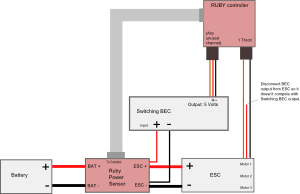
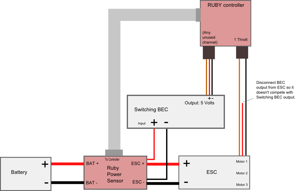
Schematic
|
click to enlarge
|
Soldering step-by-step: |
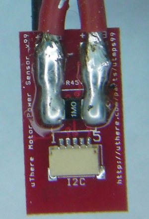
The wide copper traces through which power flows on the motor power sensor board are not sufficient to carry high current by themselves. They need a thick layer of solder on top of them to increase conductivity. Otherwise, at high power the traces can overheat and "blow" like a fuse.
Apply solder generously to cover the traces completely from the "BAT+" and "ESC+" pads all the way to each terminal of the power sense resistor. Generous solder on the power sense resistor terminals will reduce chances of it overheating and becoming inaccurate. It's ok if you get solder on top of the terminals.
|
click to enlarge |
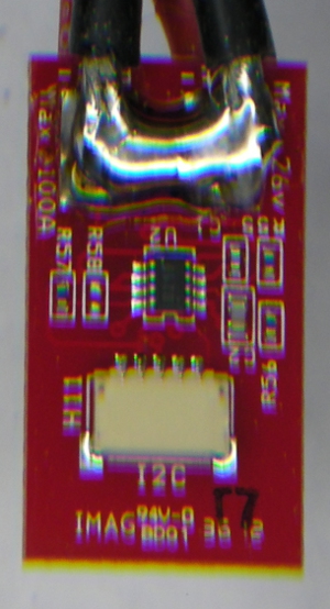
Also be sure to apply extra solder to cover the short copper trace between "BAT-" and "ESC-" on the flipside of the sensor. |
click to enlarge
|
Strip just a little bit of insulation from the end of the positve ESC power input lead and solder to the pad marked "ESC+" on the Ruby power sensor module. Solder in a position such that the uninsulated portion of the wire doesn't extend close to the edge of the board where it could short with the "ESC-" wire that will be soldered to the opposite side.
Likewise, strip and solder the negative ESC power input lead to pad marked "ESC-" the opposite side of the Ruby power sensor.
Likewise, strip and solder the pieces of wire that were cut from the ESC to the pads marked "BAT+" and "BAT -".
If a battery connector was not already attached to those wires, solder one on. Even with a small plane like the Merlin, typical motor power is 2 - 4 amps with 8 amp peaks, so we prefer larger connectors such as Dean's "T" plugs.
Solder the positive power input wire of the switching BEC in with the positive power input wire of the ESC at the "ESC+" pad on the Ruby power sensor.
Solder the negative power input wire of the switching BEC in with negative power input wire of the ESC at the "ESC-" pad on the Ruby power sensor.
*** Be sure that no uninsulated portions of wires extend beyond the edge of the Ruby power sensor. In other words, be sure that there's no way that + and - leads could possibly short if the cables are twisted in any way. |
click to enlarge |

click to enlarge |
click to enlarge |
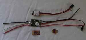
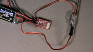
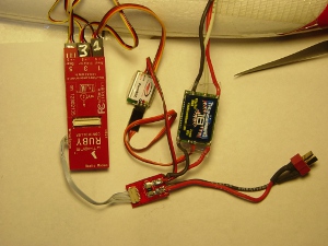
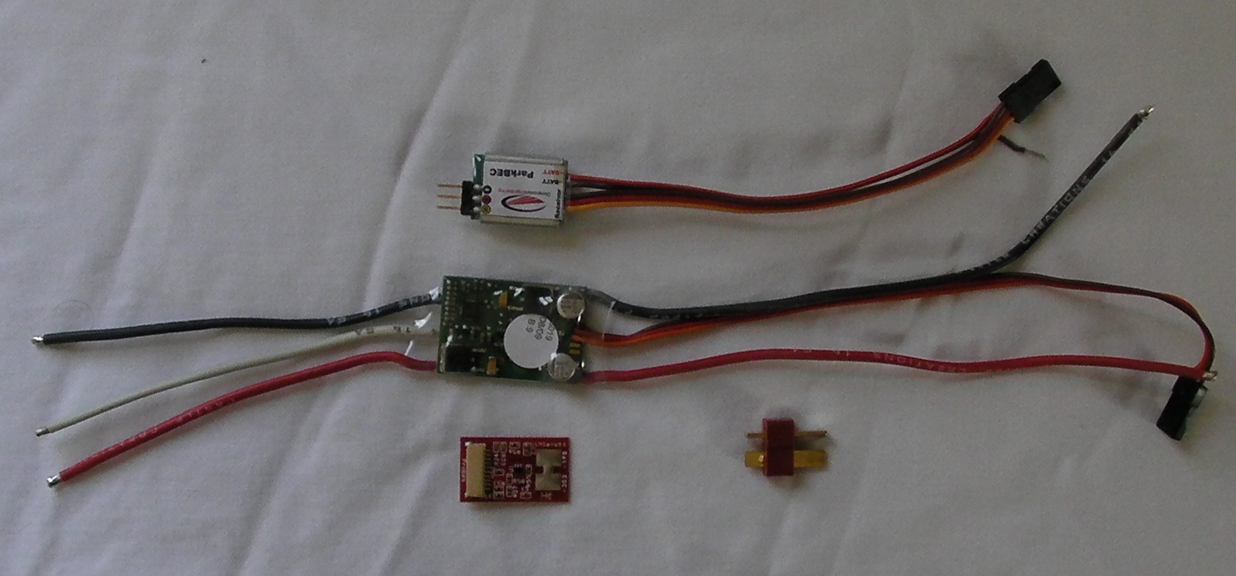
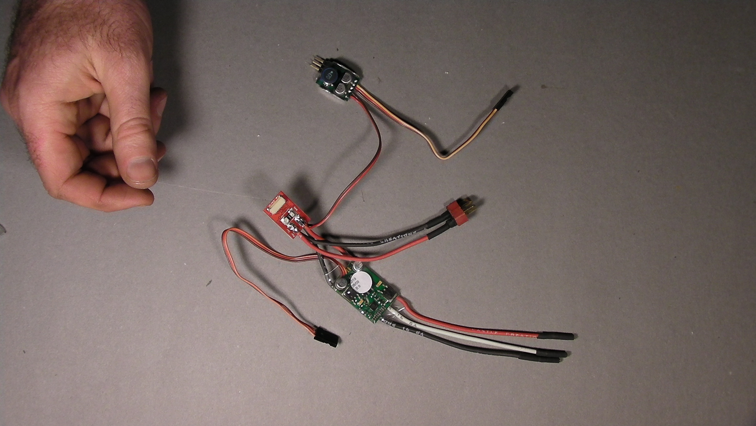
Here's what everything looks like when it's connected to Ruby,
(... except that the power sensor will be covered with electrical tape).
This picture is using a ParkBec, which combines power and throttle control into a single servo connector.
For other BECs, you'll have to plug the BEC power into an unused channel on Ruby separate from the throttle, or use a standard servo "Y" cable so the BEC can share a port with throttle or other servo. Be sure to disconnect the power wire coming in on the Throttle connector from the ESC so that the ESC's BEC and switching BEC are not trying to power the same electronics. |
click to enlarge |
Cover all exposed metal contacts.
Wrap the power sensor in electrical tape or heat shrink tubing. For easier packing, tape the power sensor to the ESC to form a single bundle. Don't wrap tape around the ESC to the extent that it becomes thermally insulated and more susceptible to overheating. |
Keep switching BEC away from GPS and R/C receivers.
In our testing, we've found that the typical BEC needs to be at least 3 inches from GPS and R/C receiver.
Note: The latest version of the motor power sensor connects to the connector labeled "I2C1" on the Ruby Controller. (Don't confuse with "I2C2" on the Expander.). The port labeled "Motor Sense" on the Ruby Controller is no longer used.
There are two connector labeled "I2C" on the power sensor. Either one can be used. The extra connector allows other I2C devices such as the airspeed/magnetometer to be daisy-chained.
|
Connecting the Ruby controller
The Controller will be inserted into the payload area with the servo pins facing aft, and large "RUBY" lettering facing down.
Servo connectors:
| Connect: |
to Ruby: |
Throttle
|
"1 Throt" |
BEC |
"5 Gear" or any other unused channel |
| Right Elevon |
"2 Ail R" |
| Left Elevon |
"6 Ail L" |
All servo connectors on the controller (but not the Expander) are connected to the same 5 volt / ground power bus.
Ribbon cable connectors:
The ribbon cables currently don't have any markings on them, but you can identify them simply by counting the number of wires.
Motor power sensor
New version: 5 wire ribbon cable, connects to "I2C1" on Ruby Controller (not "I2C2" on Expander. "Motor Sense" connector is unused).
Old version: 8 wire ribbon cable, connects to "Motor Sense" on Ruby controller.
GPS (4 wire ribbon cable - there are two such cables in your kit. Choose whichever is the most suitable length. Save the other one for use with the USB dongle)
Airspeed (5 wire ribbon cable).
Receiver (7 to 9 wire cable, depending on adapter, with a partially populated 12 wire connector that plugs into Ruby)
The "USB Dongle" and cable is just intended for temporary use on the bench. You can omit it here.
|
Other Components
For better radio reception and protection from impact, we find it best to mount GPS and radio receivers in their own pockets. Radio reception is the only consideration for placement. If possible, locate both out on one wing, and video transmitter on the opposite wing. Note that because servos are connected to Ruby rather than the receiver, it's now possible to put the receiver out on the end of a long thin cable connected to Ruby.
For best aesthetics and strength, install GPS and radio receivers before covering if possible. If you've already covered your plane, you can simply cut a flap or hole in the covering.
Many people cover their Zephyr in carbon fiber sheet. Remember that this an electromagnetic insulator. You'll need to be sure that the top of the GPS ceramic antenna is clear of carbon fiber covering and radio antenna projects out from it. There should be some margin around antennae that is free of carbon fiber. |
Balance
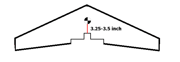
Proper balance is critical for any aircraft, whether or not a system like Ruby is in place to offer artificial stabilization. Although Ruby's "fly by wire" capability may (or may not) be able to bring an unstable plane under control, it will still fly very poorly without radical changes of settings away from standard default values, and excessive servo activity. Most notably, if the plane is a little tail heavy, Ruby control of pitch and airspeed will be erratic with standard settings, and if it's too tail heavy, the plane will be completely uncontrollable with any settings. On a flying wing, bad CG can also affect roll and yaw, not just pitch and airspeed control.
Ritewing recommends that the CG / balance point be located between 3.25 and 3.5 inches from the innermost part of the motor mount.
|
Servo control arm throw and trim
The correct servo throws and trim are critical for making the Zephyr II manageable to fly manually, and for best results with Ruby's default settings.
Ritewing recommends the following:
| Servo rates |
Elevator: 35%
In case trim is very far off, you may want to start at 45% for your maiden flight, then adjust down after your first flight.
Aileron: 55%
Ritewing does not recommend exponential, but some people feel that 40% expo works well.
Here's what the correct settings look like on the Taranis / Turnigy 9XR with OpenTX.
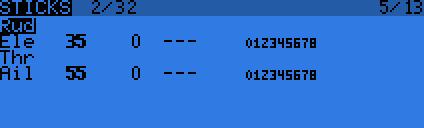
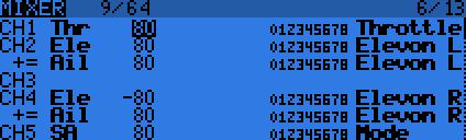
Notice that in the Taranis / Turnigy / OpenTX, weights on all channels are set to "80". [more info]
On other brand transmitters, you'll simply set the "rates" to Elevator: 35%, Aileron 55%.
|
| Control horn: |
Minimize throw:
On the servo arm, put the control rod in the innermost hole that provides clearance of the rod above the top of the wing.
On the control arm attached to the elevon, put the control rod in the hole about 3/4 inch above the top of the elevon. This is typically the outermost hole. |
| Throws |
Approximately 1/4 inch down and 3/8 inch up. |
Other components
One nice thing about a big foam wing is that you can spread out likely to interfere with each other at radio frequencies. Just pick a spot, dig out a pocket and cut a shallow groove for the ribbon cable to run to it from the controller.
We put the GPS unit in a little pocket about halfway out on one wing, and satellite receiver(s) out next to the wingtip of the same wing. We put our big 1 watt video transmitter out on the opposite wing, open to airflow for good cooling, and our digital tranceiver in the center.
The power sensor should be able to fit alongside Ruby and the ESC in the aft compartment. |
|
Cabling
Run a blade along desired cabling path to cut a groove just as deep as the cable is wide..
Even with Ruby installed, your wing may be destined for some hard knocks that really flex the wing. When running cabling, put a little slack so the cable is less likely to break or pull out of its socket if the wing flexes. You might do this by making one or more small "S" shaped folds in the cable along its route.
|
|
|
|
Configuration
Now that Ruby is physically installed, you'll need to load configuration settings to match your airframe, receiver, and preferences.
Please proceed to configuration.
|
|


![[here]](media/zephyr_ruby_installed_beautiful_large.JPG)