Installing Ruby in a Parkzone Radian and Radian Pro
|
Overview
Here are instructions, including videos and high definition closeup pictures, for installing Ruby in the Parkzone Radian (no ailerons or flaps) and Radian Pro (ailerons and flaps). For installation in other aircraft, refer to Supported Aircraft to see if specific instructions may exist. Refer to the General Installation Instructions for planes not on that list, and for more detail about some aspects of installation shown here.
The only modifications you will have to make to the Radian airframe are:
- the cutting out a small pocket on the right wing for the airspeed / magnetometer sensor,
- the slicing of a shallow channel in the wing for the airspeed / magnetometer ribbon cable (only necessary for Radian, not Radian Pro)
- the removal of a little foam from the inside of the bottom payload area to accommodate the Ruby Controller
All modifications can be made to a Radian that has already been completely assembled.
In addition, a power sensor needs to be wired between the battery and ESC.
|
| |
Mounting the airspeed / magnetometer sensor
Overview
The Ruby airspeed/magnetometer is required for Ruby operation. It must be located on a wing clear of propwash and magnetic distortion from servos. The sensor is embedded in a small pocket that you cut into the wing, similar to existing pockets for aileron servos. Mounting the sensor this way avoids adding significant drag, since nothing but the pitot tube extends into the airstream. The right wing is more preferable than the left only because of the left-facing location of the ribbon cable connector on the sensor. |

click to enlarge |
| |
Cutting the pocket
You are going to be cutting a rectangular hole in the bottom of the wing just big enough for the black box of the airspeed sensor. It will NOT extend all the way through the top surface of the wing, but it will come close. This will be similar to the holes that already exist in the wings for ailerons, but you'll also scoop out a wide, shallow indentation / shelf around that hole so that the rest of the sensor board can mount flush with the bottom of the wing. To avoid weakening the wing, all cutouts should be cut to fit the the sensor snugly, with no gaps which could allow flexing. |
| Note: besides pictures below which you can click to view in very large format close-up detail, we've created a high definition video of the cutting process for the Multiplex Merlin. This is mostly applicable to the Radian/Pro. The important difference is that for the Radian pro, you will NOT cut all the way to the top surface of the wing, and the pitot tube will be routed completely on the bottom surface of the wing, not the top. |
[Click here] to see the video at "fast forward" speed.
[Click here] to see the video at regular speed. |
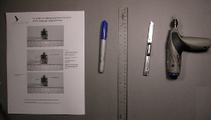
We've included in your kit a paper template that you can use to draw outlines for cuts you'll be making in the wing.
You can also download and print a fresh copy of the template from [here]. If you print this template yourself, compare the outline of the sensor to that printed on the sheet sure that the scale is correct.
|
click to enlarge |
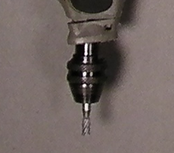
| A router bit mounted on a handheld Dremel tool will be best for the job of cutting holes and indentations in foam. |
 |
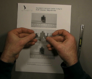
Cut out the template along all the dotted lines. You'll end up with a hole in the sheet and two smaller pieces of paper, one shaped like a "U". |
click to enlarge
|
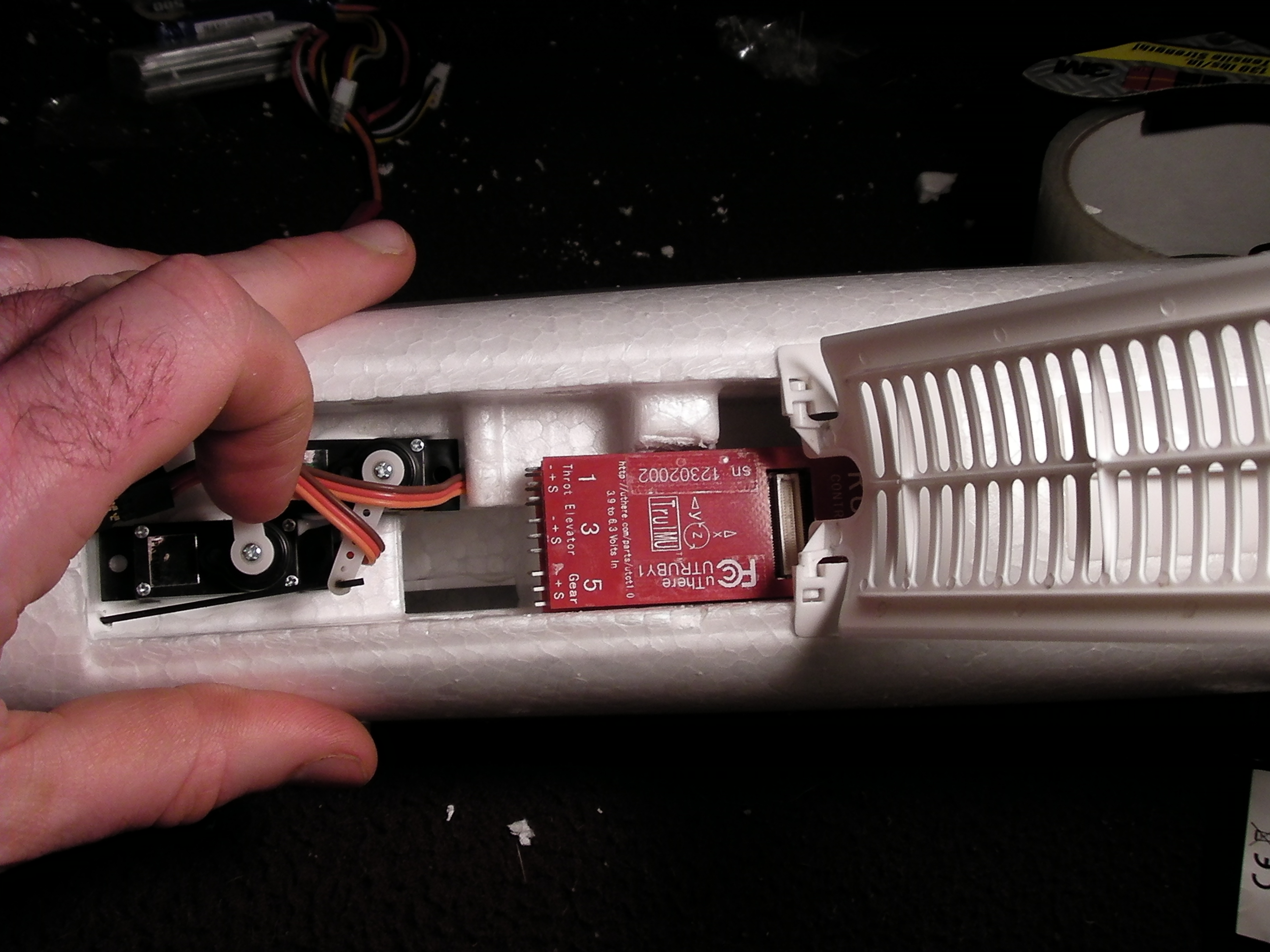
Radian Pro (ailerons/flaps): The sensor will be located between the flap and aileron servos, with the back edge of the module board just in front of the channel that already is cut in the bottom of the wing for aileron servo wiring.
Radian (no ailerons/flaps): Since there are no servos to avoid on this model, there's only propwash to avoid. The sensor can be located about halfway out on the wing, about 1 cm in front of the middle fiberglass reinforcement spar.
A good specific lateral location is at the outermost edge of the black wing marking sticker.
Radian Pro: Remove the white tape that covers the servo wire channel from this point in to the root of the wing. You will be inserting the as/mag cabling into this groove.
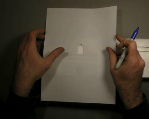
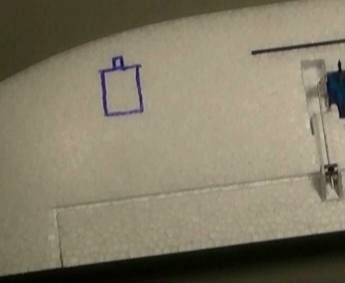
Place the template sheet on the wing with the print facing down on the wing and the nozzle facing forward. Line the hole up so it is positioned as described above. Use a marker to transfer the outline of the hole to the wing, or if there is a decal, trace a knife along the inside of the template hole to cut the decal away.
|
click to enlarge |
 |
| Place the "U" shaped piece of template with print side facing down on the wing, fitting it on the outline you just drew. Use it to draw a 'U' shaped line which will complete the outline of the deep pocket you'll scoop out for the black airspeed sensor component. |
 |
| |
 |
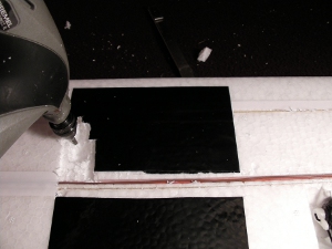
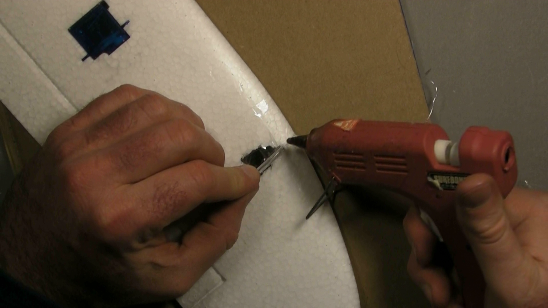
Use a dremel tool with router bit attached to carefully create the 10mm deep hole for the black box portion of the sensor.
IMPORTANT: Don't cut the deep hole for the entire board outline. Just cut the inner outline, roughly 15mm square, that corresponds to the protruding black box portion of the sensor, and cut a knotch for the airspeed sensor nozzles.
Remember that a snug fit with the sensor will give the wing more strength. Be careful not to make the hole any larger than the ink line that was drawn. Make it a little too small and shallow at first, then periodically trial-fit the airspeed sensor as you make the hole a little wider and deeper as necessary. |
 |
Clear out foam about 1.5mm deep from the remainder of the board outline. Again, periodically trial-fit the sensor to see where more foam needs to be cleared and to assure snuggest fit. You'll have to create small indentations in some places for some of the components on the sensor board.
|
 click to enlarge click to enlarge |
|
|
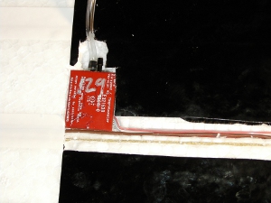
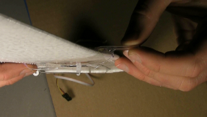
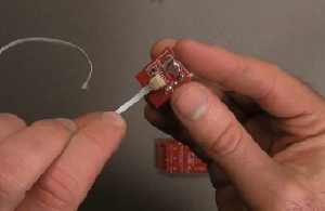
Rather than use a hard pitot tube which can snag on obstacles and cause damage, the pitot tube used by Ruby is a 1/8'' diameter clear piece of semi-flexible PVC tubing that is made just stiff enough with hot glue at the base to avoid flexing during flight.
Slide one end of pitot tubing over the TOP nozzle of the airspeed sensor. (The tubing would route more nicely if the pitot tube could connect to the bottom nozzle instead of the top, but that's not the case. The bottom nozzle is the 'static' port and must be left open to ambient pressure.)
Plug the 5 wire ribbon cable into the sensor.
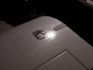
Insert the sensor into the pocket that you've made.
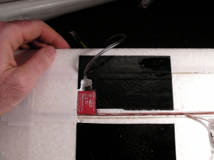
The pitot tubing has to bend down to exit the bottom of the wing where it will run forward on the bottom surface of the wing to the leading edge. Be sure the tube is not kinked / blocked as it makes this bend. Remove more foam from the front of the top nozzle if necessary.
Make sure the complete sensor board is seated flush with the bottom of the wing. Remove more foam if necessary.
|
 click to enlarge click to enlarge |
 click to enlarge click to enlarge |
You can simply glue the pitot tube to the bottom of the wing, or you can dig out a channel for the pitot to allow it to mount flush with the bottom of the wing all the way to the leading edge for a little better streamlining and aesthetics. The drawaback of the channel is that you'll have to grind a knotch out of the front fiberglass spar, possibly weakening it slightly.
|
 click to enlarge click to enlarge |
Hot-gluing the pitot tube
|
Note: In addition to the pictures below which can be clicked to access large high-resolution closeups, a high-definition video is available.
The pictures and video are actually for a Merlin, but mostly applicable to the Radian Pro. The main difference is that the Merlin airspeed tube is mounted on the top of the wing, while the Radian is mounted on the bottom. |
[Click here] to see the video at "fast forward" speed.
[Click here] to see the video at regular speed. |
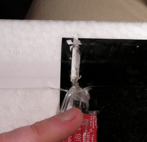
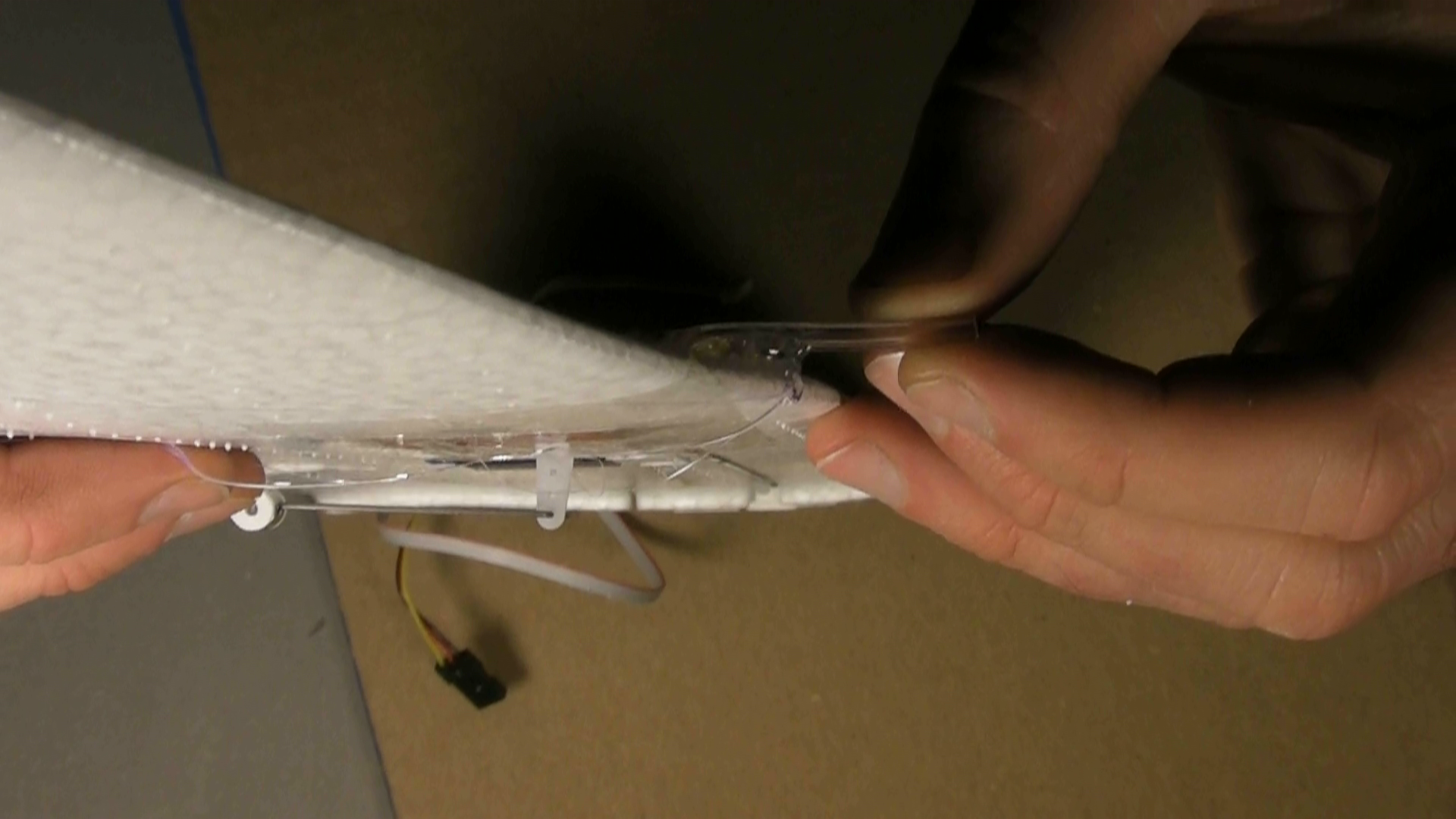
Hot glue is used to provide support and stiffening of the tube base to ensure that it always extends into the airstream parallel to the bottom of the wing.
Lift the pitot tube from the wing (but don't unplug it it from the airspeed sensor), and apply hot glue on the wing beneath.
Lower the tube onto the glue, and move side to side and twist back and forth so that the glue wraps around the tube and forms a base around it.
Apply a little more glue to the top of the tube to ensure that the glue completely encircles the tubing at its base, thus holding the tube mechanically rather than purely by adhesion.
|

click to enlarge |
As the glue cools, hold the tubing out at so that it is parallel to the bottom of the wing and to the plane fuselage, and will thus point directly into airstream during normal cruise flight. The glue should form a kind of "pylon".
You might add additional hot glue after the original glue cools to form a stronger base. |
click to enlarge |
Trim the pitot tube so that just 20 mm extends beyond the leading edge of the wing.
Be sure to cut the tubing square, so that the face of the tube will be perpendicular to airflow.
|
|
|
|
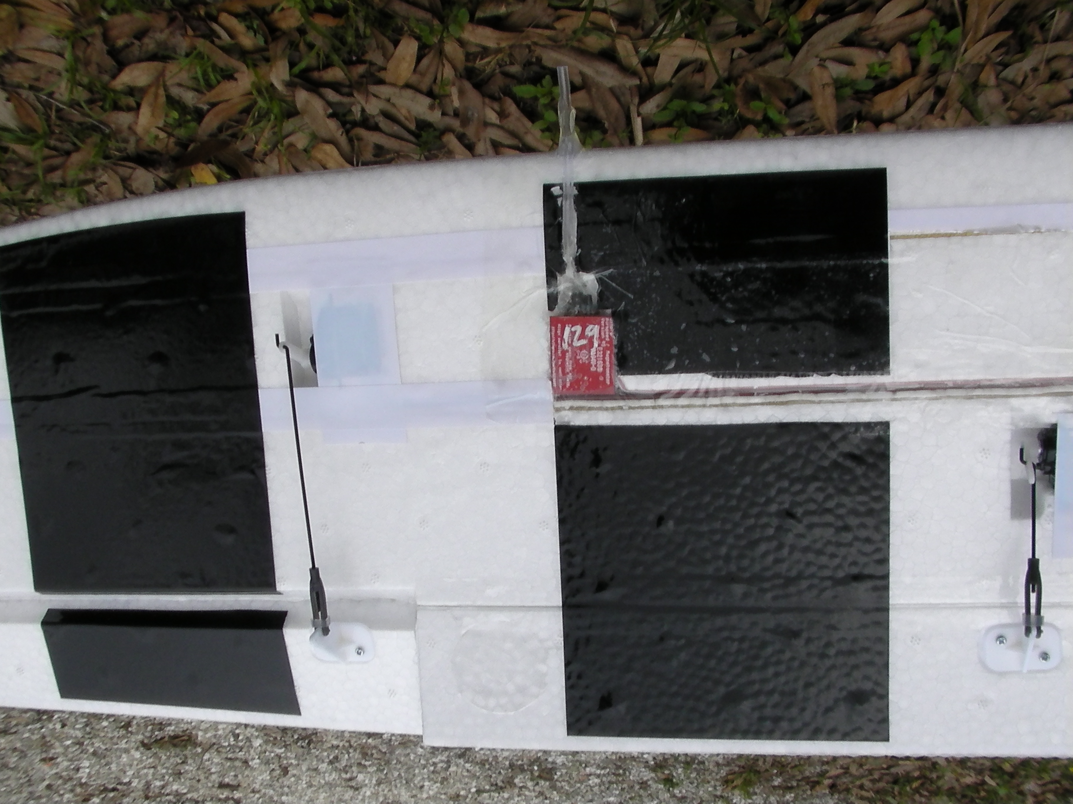
Routing the wiring
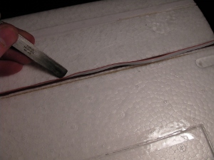
Radian Pro: Tuck the sensor ribbon cable into the channel alongside the aileron servo wire all the way to the wing root. A dull flat object like a butter knife may be helpful. You may also find it easier to pull the existing servo wires out of the groove, then tuck them back in together with the ribbon cable.
Radian: Use a sharp knife to cut a shallow channel in the bottom of the wing running from the connector on the airspeed / magnetometer sensor to the root of the wing. Make the cut only as deep as the 5-wire cable is wide (3mm). Tuck the cable into this channel. A dull flat object like a butter knife may be helpful. |
click to enlarge
|
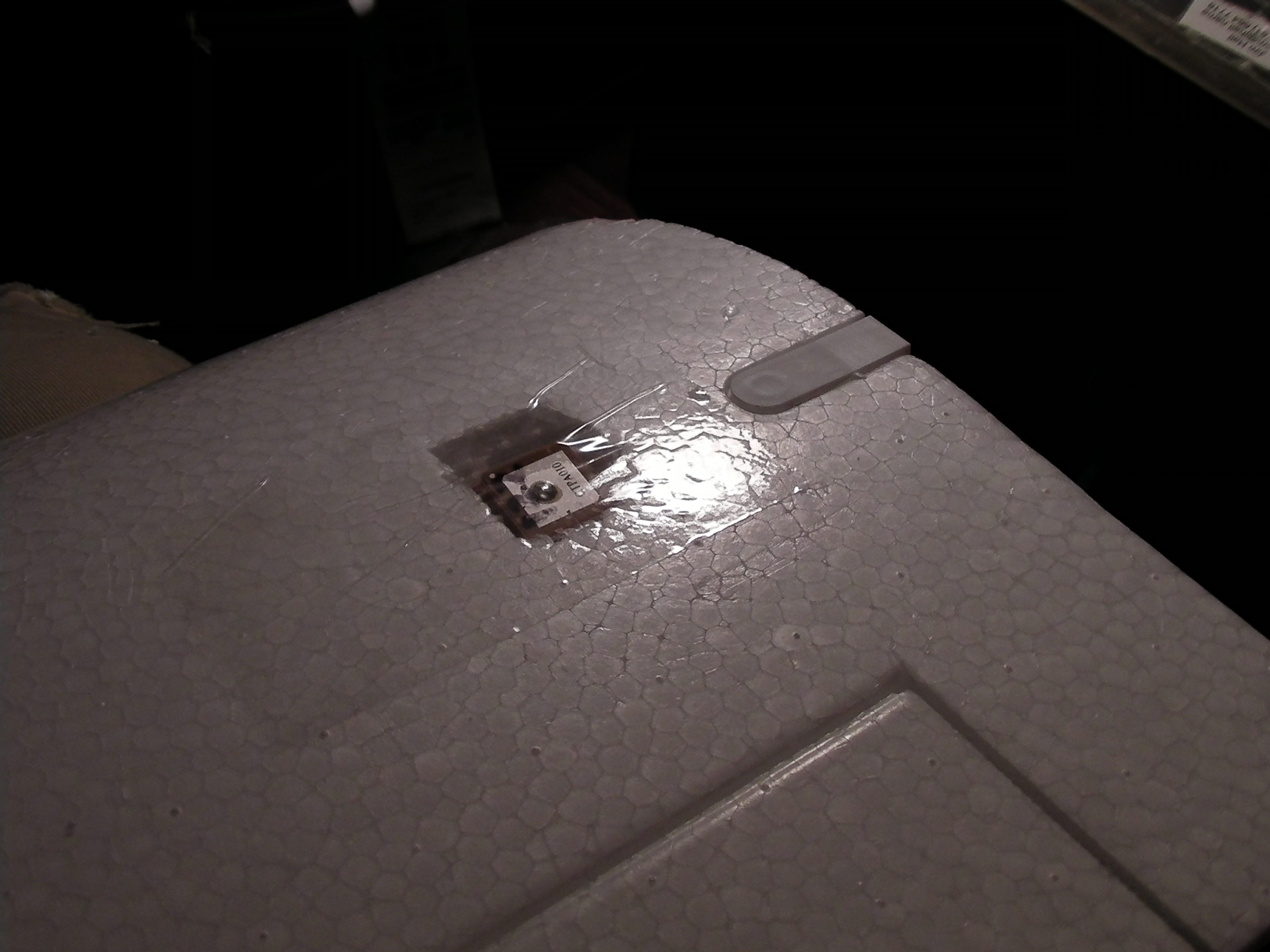
Apply a piece of wide packing tape to the bottom of the sensor and surrounding wing and on top of the servo wire channel all the way back to the wing root. This holds the sensor and wiring in place, allows for easy removal / transfer, restores some strength to the wing and provides slightly smoother airflow over the indentations.
|
click to enlarge |
The pocket / chamber in which the sensor resides serves as the "static port", and needs to be at ambient air pressure during flight.
Poke a hole in this tape below the airspeed sensor nozzles to be sure that the chamber is not airtight. |
click to enlarge
|
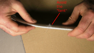
| Be sure that the tape does not form a forward facing "tent" on top of the airspeed pitot that could "scoop" air and pressurize the chamber / static air measurement during flight. This would lead to inaccurately low airspeed readings and poor IMU performance. |
click to enlarge |
|
Wiring the power sensor and switching regulator
Overview
Ruby currently requires a power sensor to enable it to control motor power with precision and track remaining battery capacity. You can fly Ruby without it connected, but you'll lose altitude hold, autonomous landing, and battery gauge capabilities.
We also recommend using a "Switching BEC" to power Ruby. See input power requirements.
To conserve space when installing in smaller planes, it's recommended that these parts be soldered together rather than add the bulk of additional connectors. |
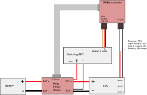
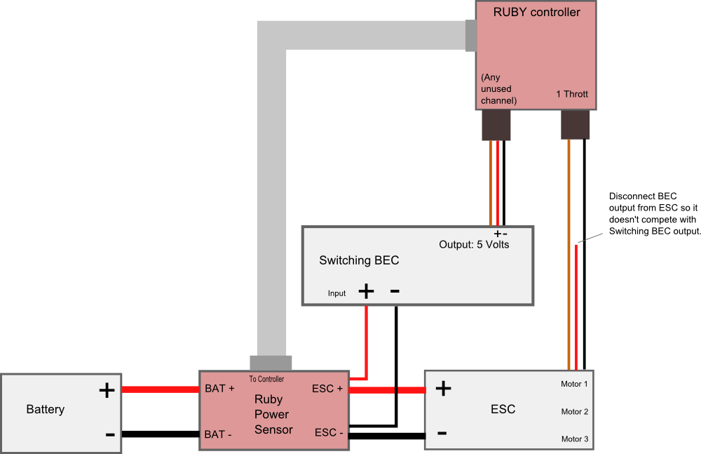
Schematic
|
click to enlarge
|
Soldering step-by-step: |
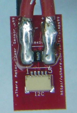
The wide copper traces through which power flows on the motor power sensor board are not sufficient to carry high current by themselves. They need a thick layer of solder on top of them to increase conductivity. Otherwise, at high power the traces can overheat and "blow" like a fuse.
Apply solder generously to cover the traces completely from the "BAT+" and "ESC+" pads all the way to each terminal of the power sense resistor. Generous solder on the power sense resistor terminals will reduce chances of it overheating and becoming inaccurate. It's ok if you get solder on top of the terminals.
|
click to enlarge |
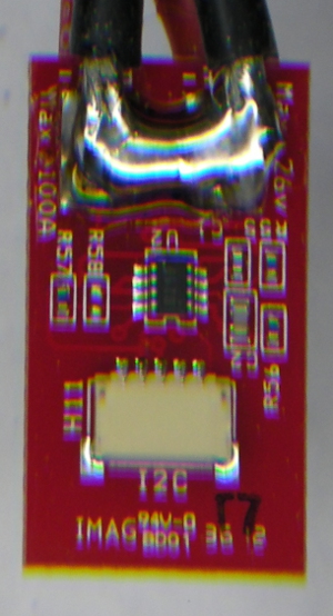
Also be sure to apply extra solder to cover the short copper trace between "BAT-" and "ESC-" on the flipside of the sensor. |
click to enlarge
|
Strip just a little bit of insulation from the end of the positve ESC power input lead and solder to the pad marked "ESC+" on the Ruby power sensor module. Solder in a position such that the uninsulated portion of the wire doesn't extend close to the edge of the board where it could short with the "ESC-" wire that will be soldered to the opposite side.
Likewise, strip and solder the negative ESC power input lead to pad marked "ESC-" the opposite side of the Ruby power sensor.
Likewise, strip and solder the pieces of wire that were cut from the ESC to the pads marked "BAT+" and "BAT -".
If a battery connector was not already attached to those wires, solder one on. Even with a small plane like the Merlin, typical motor power is 2 - 4 amps with 8 amp peaks, so we prefer larger connectors such as Dean's "T" plugs.
Solder the positive power input wire of the switching BEC in with the positive power input wire of the ESC at the "ESC+" pad on the Ruby power sensor.
Solder the negative power input wire of the switching BEC in with negative power input wire of the ESC at the "ESC-" pad on the Ruby power sensor.
*** Be sure that no uninsulated portions of wires extend beyond the edge of the Ruby power sensor. In other words, be sure that there's no way that + and - leads could possibly short if the cables are twisted in any way. |
click to enlarge |

click to enlarge |
click to enlarge |
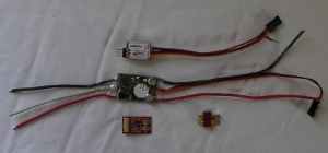
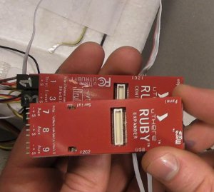
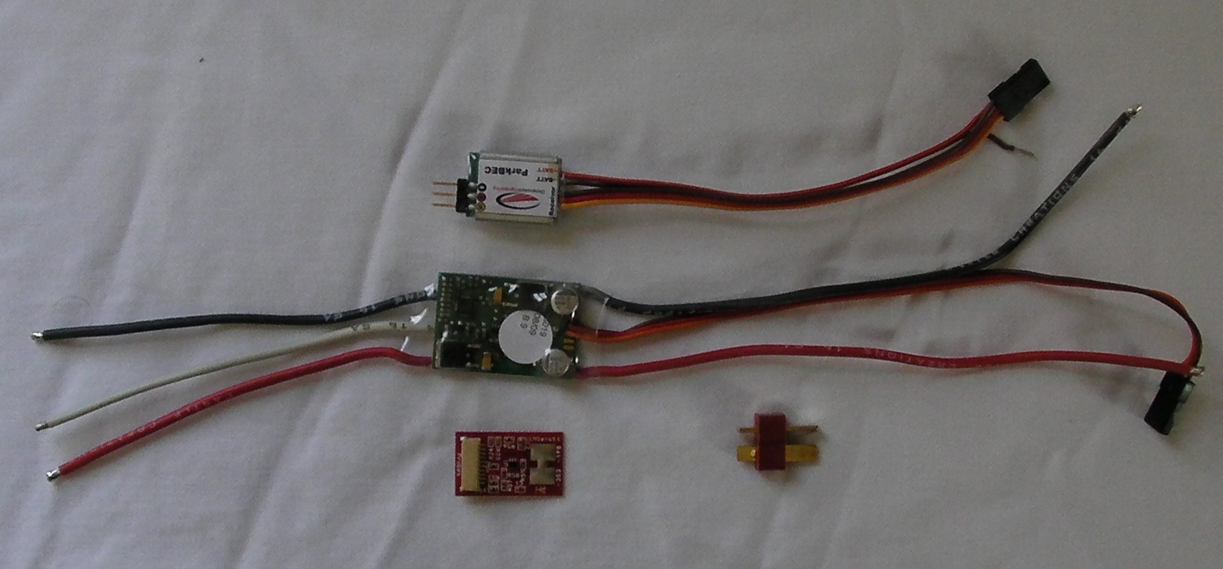
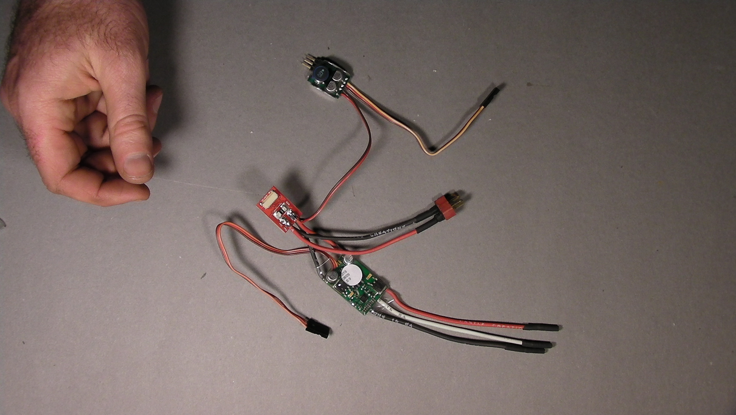
Here's what everything looks like when it's connected to Ruby,
(... except that the power sensor will be covered with electrical tape).
This picture is using a ParkBec, which combines power and throttle control into a single servo connector.
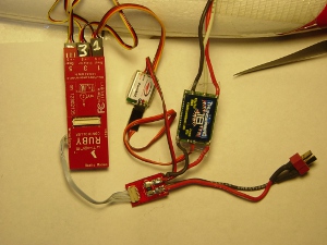
For other BECs, you'll have to plug the BEC power into an unused channel on Ruby separate from the throttle, or use a standard servo "Y" cable so the BEC can share a port with throttle or other servo. Be sure to disconnect the power wire coming in on the Throttle connector from the ESC so that the ESC's BEC and switching BEC are not trying to power the same electronics. |
click to enlarge |
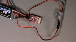
Cover all exposed metal contacts.
Wrap the power sensor in electrical tape or heat shrink tubing. For easier packing, tape the power sensor to the ESC to form a single bundle. Don't wrap tape around the ESC to the extent that it becomes thermally insulated and more susceptible to overheating. |
Keep switching BEC away from GPS and R/C receivers.
In our testing, we've found that the typical BEC needs to be at least 3 inches from GPS and R/C receiver.
Note: The latest version of the motor power sensor connects to the connector labeled "I2C1" on the Ruby Controller. (Don't confuse with "I2C2" on the Expander.). The port labeled "Motor Sense" on the Ruby Controller is no longer used.
There are two connector labeled "I2C" on the power sensor. Either one can be used. The extra connector allows other I2C devices such as the airspeed/magnetometer to be daisy-chained.
|
Getting everything to fit
As big as the Radian / Pro is, the open payload area is relativley small. Nevertheless, A complete Ruby system, including Expander if desired, will fit along with other standard aircraft motor, electronics and a good sized battery, and even FPV gear.
We provide some placement suggestions here, but other than being sure that Ruby is mounted in line with the plane logitudinal axis and keeping the GPS and control receiver away from FPV transmitter, there are no hard constraints, and you're welcome to be creative.
|
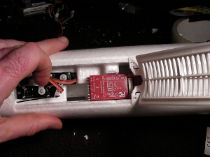
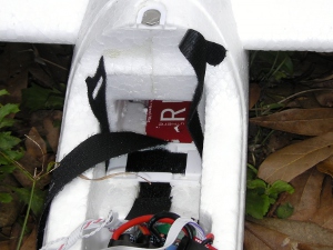
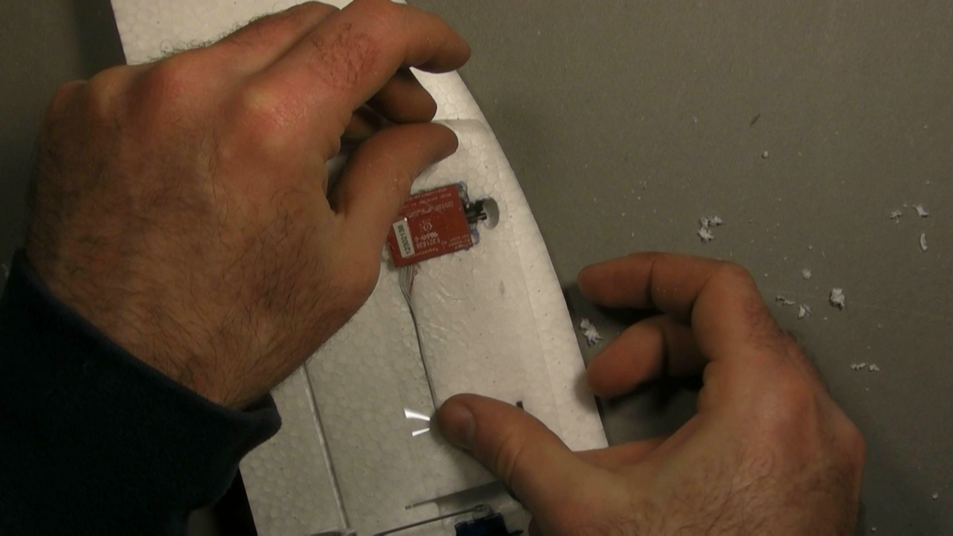
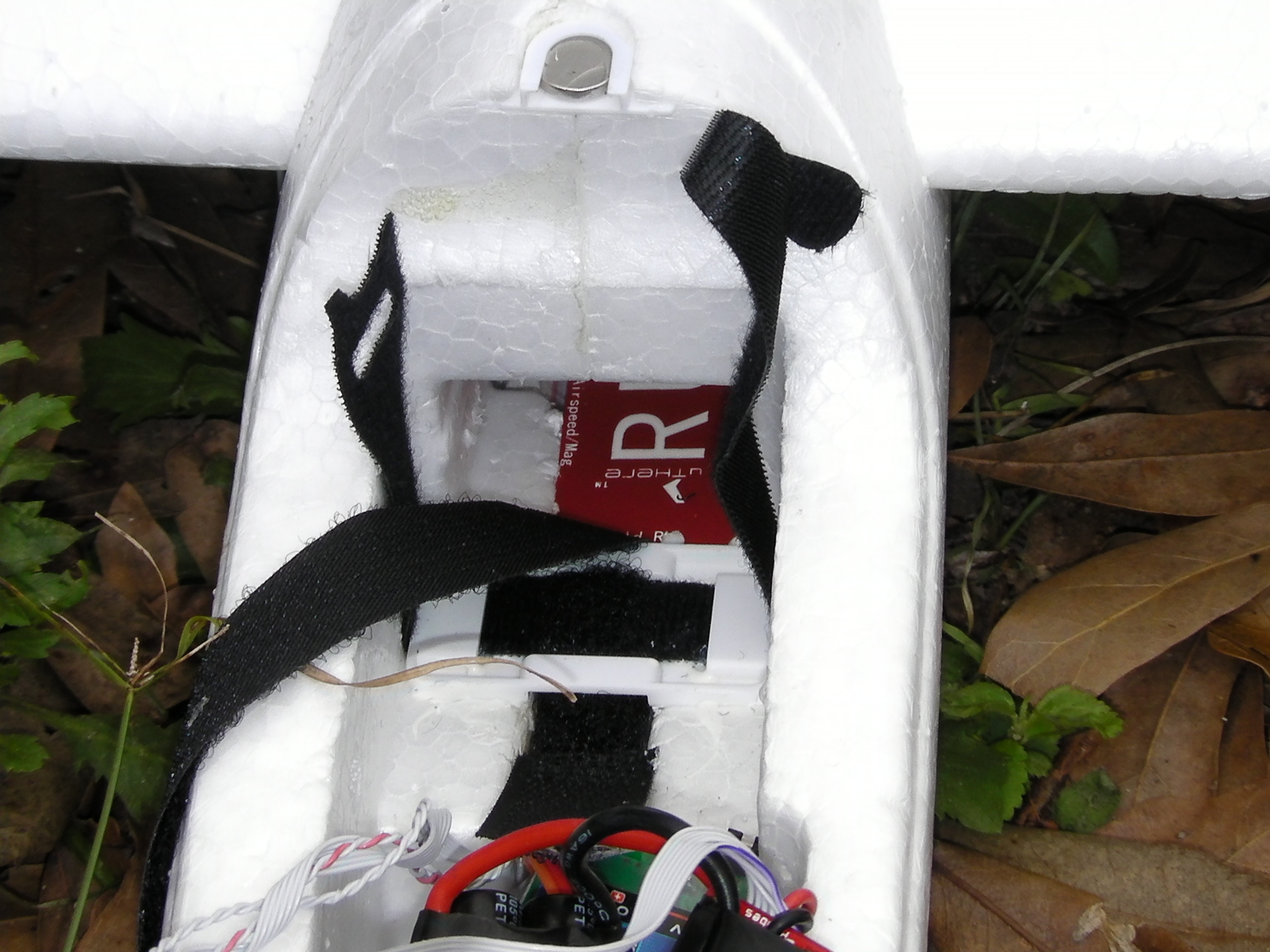
Placement of the Ruby Controller
All else considered, there seems to be just one ideal location in the Radian / Radian Pro for the Ruby controller which makes best use of space and requires a minimum of modification to the fuselage. That's in the bottom payload area, beneath the back half of the battery compartment. See the images to the right:
It is necessary to chip away some foam for this placement, but not much.
** Be sure that the Ruby controller is mounted in line with the plane axes, not at any angle. This is necessary for proper IMU operation. In particular, make sure that the controller is not tilted up or down.
For compatability with standard configuration files provided by uThere, insert Ruby with the large "RUBY" lettering facing up, not down.
|
click to enlarge
|
| |
click to enlarge |
Placement of GPS and R/C Receiver |
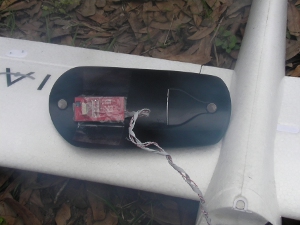
We've found that our GPS and typical remote control receivers don't interfere with each other and can be located together if desired. They also seem fairly tolerant of proximity to the ESC. So, it's easiest to attach them to the inside of the cockpit canopy.
|
click to enlarge
|
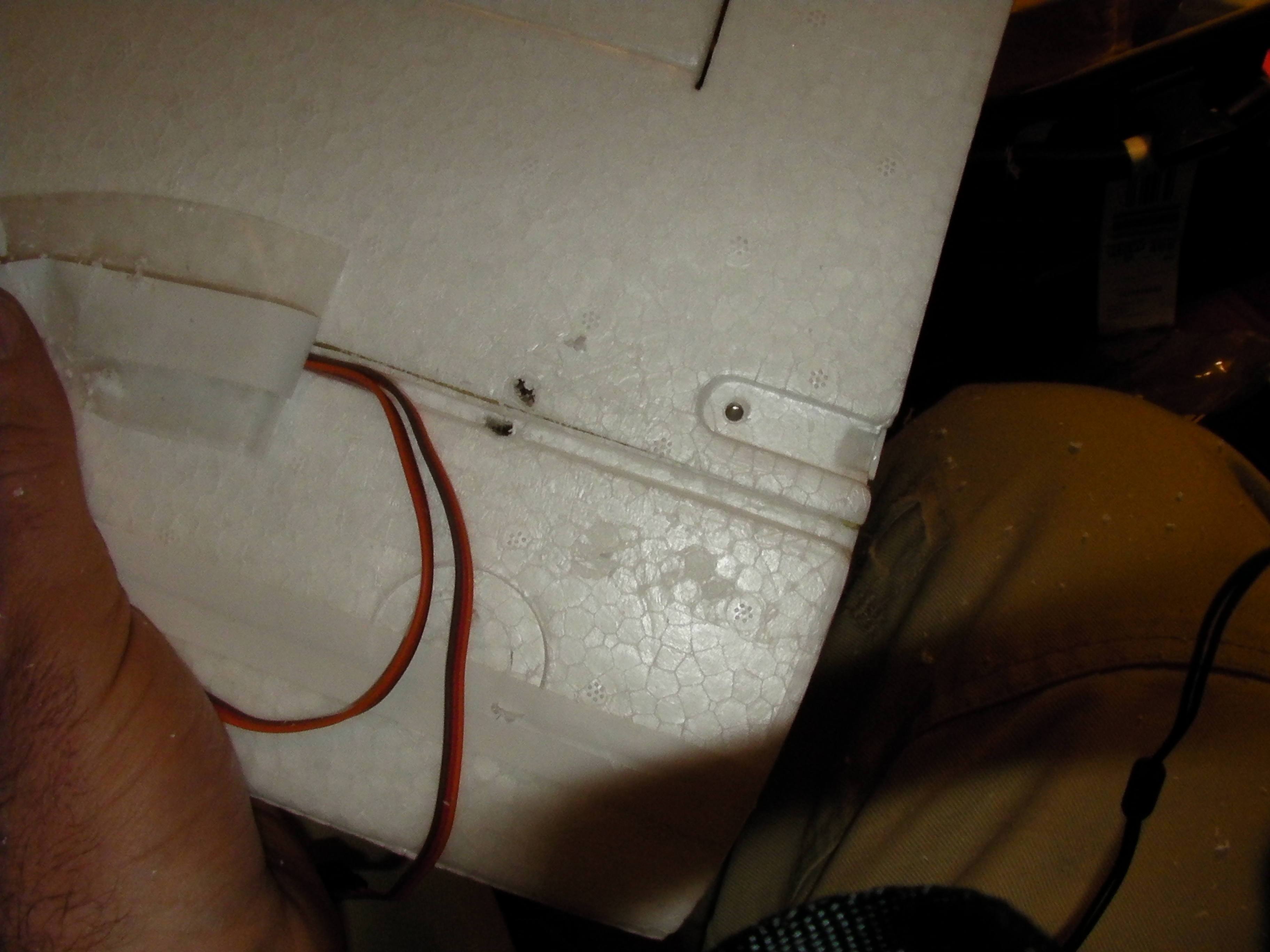
If you have FPV camera and transmitter, you might need to get more creative, however, since you'll most commonly want to put camera and transmitter together in the cockpit and a transmitter should not be located close to these receivers.
In our case, we made a concession to drag by placing the receiver outside the fuselage. Fortunately, since servos now connect to Ruby instead of the receiver, only a thin cable needs to run outside the fuselage to the receiver.
A more ideal location for the receiver might be in a pocket carved out of the the fuselage behind the wing. We didn't have the nerve to dig out that much foam.
|

click to enlarge |
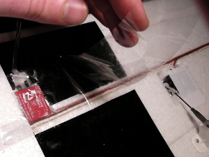
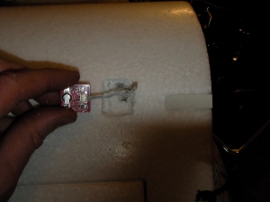
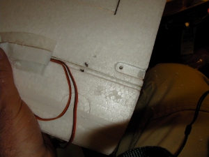
| We decided to embed the GPS in the top of the wing, covering with clear tape to restore smooth airflow. |
click to enlarge |
| |
click to enlarge |
| |
click to enlarge |
| |
|
Connecting the Ruby Controller |
We've created a video showing connection of all the cables
|
[Click here] to see the video at "fast forward" speed.
[Click here] to see the video at regular speed. |
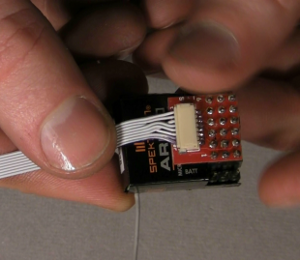
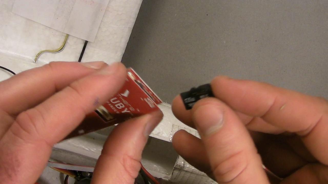
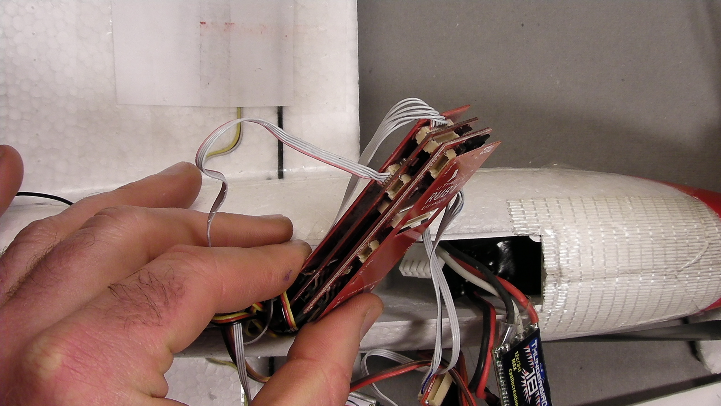
If you'd like to have flight data recording (and we recommend doing so whenever possible), plug the Expander into the Controller before inserting into the Radian. Be sure that all the servo pins on the expander are facing in the same direction as those on the controller. You might have to carve out more foam for the extra thickness.
The "expander spanner" is only necessary if you want to use any of the servo channels on the Expander. |
click to enlarge |
Don't forget to insert your SD flash chip into the expander.
For flight data recording to occur, that chip must have a folder named 'ruby' with a file ending in ".UTMS" file on it. [more info..] |

click to enlarge |
Attach the receiver adapter to your receiver and plug in the cable. |
click to enlarge |
| |
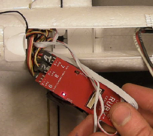
The Controller will be inserted into the payload area with the servo pins facing aft, and large "RUBY" lettering facing up.
Hold it in this orientation as you begin to plug all cabling into the Ruby controller to minmize twisting of cables:
Servo connectons:
| Connect: |
to Ruby: |
Throttle
(and BEC if Parkbec) |
"1 Thrott" |
| Right Aileron |
"2 Ail R" |
| Elevator |
"3 Elev" |
| Rudder |
"4 Rudd" |
Flaps
(using "Y" cable connected to both flaps servos) |
"5 Gear" |
| Left Aileron |
"6 Ail L" |
If you don't have a Parkzone BEC that feeds power through the throttle servo connector, you'll have to use the "Expander Spanner" to provide an extra place to plug the BEC in.
Be sure to plug servos and BEC into Ruby with correct polarity. Plugging the BEC in with polarity reversed could destroy your Ruby! Black wires should match with "-" printed on Ruby cover for every channel.
Ribbon cable connectors:
The ribbon cables currently don't have any markings on them, but you can identify them simply by counting the number of wires.
Motor power sensor
New version: 5 wire ribbon cable, connects to "I2C1" on Ruby Controller (not "I2C2" on Expander. "Motor Sense" connector is unused).
Old version: 8 wire ribbon cable, connects to "Motor Sense" on Ruby controller.
GPS (4 wire ribbon cable - there are two such cables in your kit. Choose whichever is the most suitable length)
Airspeed (5 wire ribbon cable).
Receiver (7 to 9 wire cable, depending on adapter, with a partially populated 12 wire connector that plugs into Ruby)
The "USB Dongle" and cable is currently just intended for temporary use on the bench, so you can omit it from flight configuration. (In the future, you might use it in the field to check plane status in detail before flying.)
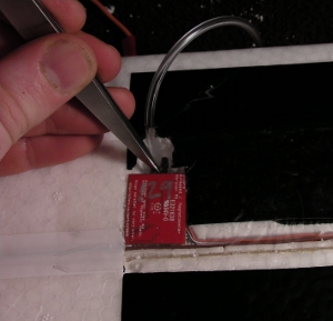
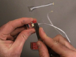
The best way to insert a small ribbon cable plug is to gently insert it slightly into the receptacle just enough to line it up, then press firmly into place by pushing something like a wide screwdriver blade against the plastic at the back of the plug. Don't try to use your fingernail, because the wedging action of your fingertip may pry the controller's cover off.
|
|
| The best way to insert a small ribbon cable plug is to gently insert it slightly into the receptacle just enough to line it up (you can hold it by the wires), then press firmly into place by pushing something like a butter knife or wide screwdriver blade against the plastic at the back of the plug. Don't try to use your fingernail, because the wedging action of your fingertip may pry the controller's cover off. |
|
Before proceeding further, this is a good time to review connections and polarities, turn on your transmitter, apply power to Ruby, and make sure Ruby and everything else is working correctly. Turn on your transmitter and make sure all servos move.
Beware the Ruby-controlled propeller. [See warnings]
If the Expander is attached, the red and green lights should flash alternately for a few seconds when power is applied, then the red and/or green light should blink in various patterns to indicate whether plane and autopilot are ready for flight. (Green light by itself means everything is OK including GPS lock, battery voltage, and receipt of good signal from your transmitter, but GPS lock might be difficult if you are testing indoors, so you'll more likely see red flashing light.) |
 |
Now, unplug the battery and insert Ruby into the payload area..
Be sure that the controller is lined up with the longitudinal axis of the plane. This orientation is critical for proper IMU operation. |
click to enlarge |
|
| |
Balance
Follow manufacturer's directions regarding balance of the plane.
Proper balance is critical for any aircraft, whether or not a system like Ruby is in place to offer artificial stabilization. Although Ruby's "fly by wire" capability may (or may not) be able to bring an unstable plane under control, it will still fly very poorly without radical changes of settings away from standard default values, and excessive servo activity. Most notably, if the plane is a little tail heavy, Ruby control of pitch and airspeed will be erratic with standard settings, and if it's too tail heavy, the plane will be completely uncontrollable with any settings. |
|
Configuration
Now that Ruby is physically installed, you'll need to load configuration settings to match your airframe, receiver, and preferences.
Please proceed to configuration. |
|


