Wiring the power sensor and switching regulator
Overview
Ruby currently requires a power sensor to enable it to control motor power with precision and track remaining battery capacity. You can fly Ruby without it connected, but you'll lose altitude hold, autonomous landing, and battery gauge capabilities.
We also recommend using a "Switching BEC" to power Ruby. See input power requirements.
To conserve space when installing in smaller planes, it's recommended that these parts be soldered together rather than add the bulk of additional connectors.
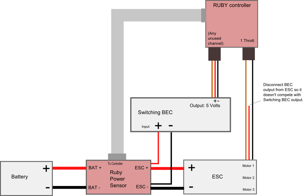
Schematic
Soldering step-by-step:
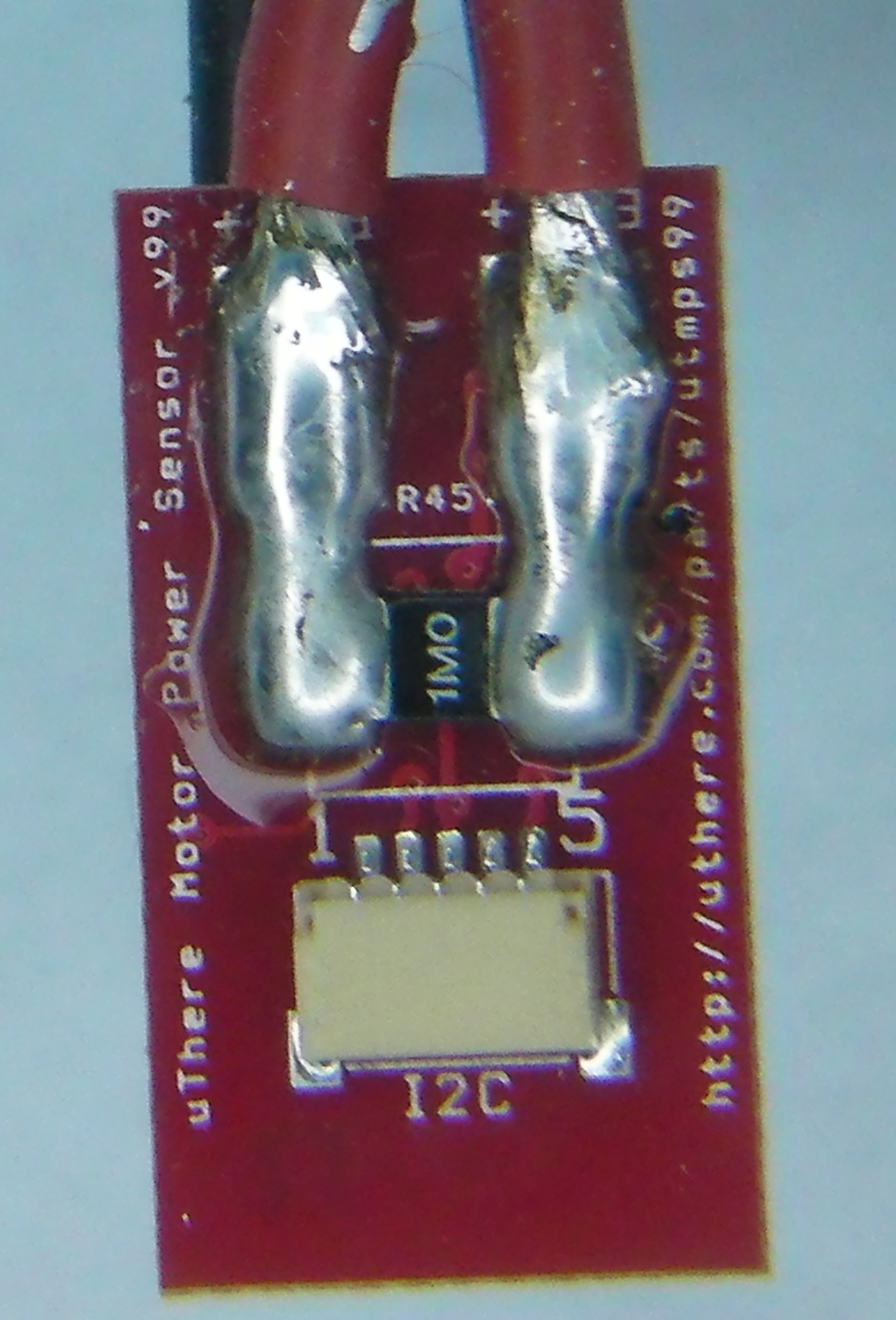
The wide copper traces through which power flows on the motor power sensor board are not sufficient to carry high current by themselves. They need a thick layer of solder on top of them to increase conductivity. Otherwise, at high power the traces can overheat and "blow" like a fuse.
Apply solder generously to cover the traces completely from the "BAT+" and "ESC+" pads all the way to each terminal of the power sense resistor. Generous solder on the power sense resistor terminals will reduce chances of it overheating and becoming inaccurate. It's ok if you get solder on top of the terminals.

click to enlarge
Also be sure to apply extra solder to cover the short copper trace between "BAT-" and "ESC-" on the flipside of the sensor.
Strip just a little bit of insulation from the end of the positve ESC power input lead and solder to the pad marked "ESC+" on the Ruby power sensor module. Solder in a position such that the uninsulated portion of the wire doesn't extend close to the edge of the board where it could short with the "ESC-" wire that will be soldered to the opposite side.
Likewise, strip and solder the negative ESC power input lead to pad marked "ESC-" the opposite side of the Ruby power sensor.
Likewise, strip and solder the pieces of wire that were cut from the ESC to the pads marked "BAT+" and "BAT -".
If a battery connector was not already attached to those wires, solder one on. Even with a small plane like the Merlin, typical motor power is 2 - 4 amps with 8 amp peaks, so we prefer larger connectors such as Dean's "T" plugs.
Solder the positive power input wire of the switching BEC in with the positive power input wire of the ESC at the "ESC+" pad on the Ruby power sensor.
Solder the negative power input wire of the switching BEC in with negative power input wire of the ESC at the "ESC-" pad on the Ruby power sensor.
*** Be sure that no uninsulated portions of wires extend beyond the edge of the Ruby power sensor. In other words, be sure that there's no way that + and - leads could possibly short if the cables are twisted in any way.
click to enlarge
click to enlarge

click to enlarge
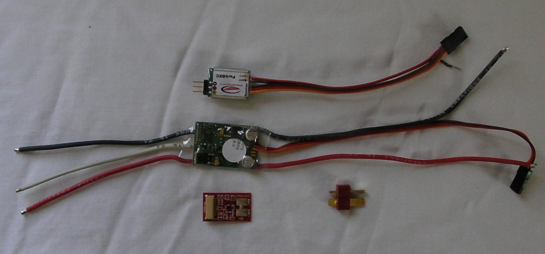
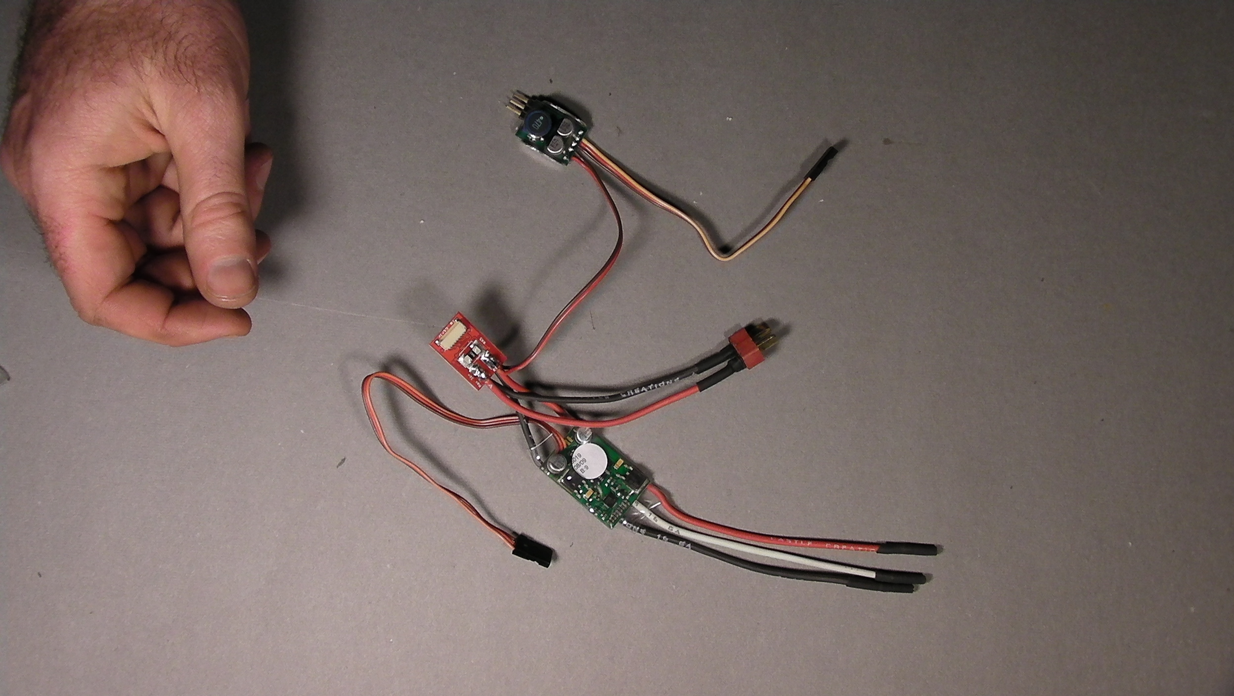
Here's what everything looks like when it's connected to Ruby,
(... except that the power sensor will be covered with electrical tape).
This picture is using a ParkBec, which combines power and throttle control into a single servo connector.
For other BECs, you'll have to plug the BEC power into an unused channel on Ruby separate from the throttle, or use a standard servo "Y" cable so the BEC can share a port with throttle or other servo. Be sure to disconnect the power wire coming in on the Throttle connector from the ESC so that the ESC's BEC and switching BEC are not trying to power the same electronics.

click to enlarge
Cover all exposed metal contacts.
Wrap the power sensor in electrical tape or heat shrink tubing. For easier packing, tape the power sensor to the ESC to form a single bundle. Don't wrap tape around the ESC to the extent that it becomes thermally insulated and more susceptible to overheating.
Keep switching BEC away from GPS and R/C receivers.
In our testing, we've found that the typical BEC needs to be at least 3 inches from GPS and R/C receiver.
Note: The latest version of the motor power sensor connects to the connector labeled "I2C1" on the Ruby Controller. (Don't confuse with "I2C2" on the Expander.). The port labeled "Motor Sense" on the Ruby Controller is no longer used.
There are two connector labeled "I2C" on the power sensor. Either one can be used. The extra connector allows other I2C devices such as the airspeed/magnetometer to be daisy-chained.